A Second
DIY Garden Heliochronometer
by Brian Huggett
The link to the page
that describes my first heliochronometer is at:
http://bit.ly/The_Huggett_Heliochronometer
The link to the page that describes my third heliochronometer
is at:
http://bit.ly/The_Huggett_Heliochronometer_Mark_III
Contents:
Introduction – The introduction below describes how I came to make two heliochronometers. If you are simply interested in the design, construction and functioning of Mark II, please skip this section.
The Huggett Heliochronometer (Mark II) – Design, Construction and Functioning
~*~*~*~*~*~*~*~*~*~*~*~
 |
 |
~*~*~*~*~*~*~*~*~*~*~*~
This introduction describes how I came to make two heliochronometers. If you are simply interested in the design, construction and functioning of Mark II, please skip this section.
A detailed description of my first heliochronometer (Mark I) can be found at: http://bit.ly/The_Huggett_Heliochronometer. That webpage also describes the underlying physics and my solutions to some of the construction issues.
My wife and I enjoy visiting gardens, in part to gain inspiration for our own. Such outings in the summer of 2016 led me to consider installing a sundial in our garden.
Knowing little about sundials, I inspected those we encountered and was dismayed to discover that none agreed with my watch. Even those that claimed to reflect clock time required additional consultation of a table or graph.
‘What we need,’ I said to my wife, ‘is a sundial from which clock time can easily be read by anyone.’
‘Why don’t you make one?’ she replied.
I decided to pursue her suggestion, and undertook research into sundials – specifically I looked at those from which clock time could be directly read – heliochronometers.
I thought this might be an interesting project, but I had little expectation that I would ultimately construct a device from which clock time could be read to an accuracy of within one minute.
It was pleasant surprise to achieve that objective, but a greater surprise was the interest taken in my heliochronometer by the British Sundial Society (the BSS) and in particular its chairman, Dr. Frank King. I remain very grateful to Dr. King for his interest, enthusiasm and advice.
Contact with the BSS resulted in my sundial being the subject of an article in the September 2017 edition of its magazine, the Bulletin. It also led to me delivering a short talk about it to a BSS meeting in Newbury, Berkshire, in the same month.
I had originally viewed my heliochronometer as a one-off project, and had never intended to build a second. Several factors, however, combined to change my mind.
These factors were:
*Use of my heliochronometer during 2017 allowed me to consider
which features of the instrument had worked well and which could
be improved upon.
*The construction of my first heliochronometer had taught me
various skills and techniques that I could employ if building a
similar instrument.
*A member of the BSS said that he would like to construct a
similar heliochronometer. I had to explain, however, that it
remained a work in progress – closer to the Wright brothers’
aircraft than to a Spitfire and, as such, not at a stage at which
it could be simply copied. Also no plans could be shared because
there were none – I had designed it as I went along.
*At the BSS meeting in Newbury in September 2017, I met with a
member, Kevin Karney, who showed me how a Pilkington Sol
Horometer corrects for the Equation of Time. He also suggested
the use of PTFE (Teflon*) as a way to minimise friction or
adhesion between two moving surfaces.
I realised that the Sol Horometer principle was the last piece in a jigsaw that would allow me to make a heliochronometer that resolved all the problematic elements of my first instrument in far more elegant ways.
This new heliochronometer, although having the same size of timescale as my first, would also be a smaller and more portable instrument that, with a few simple plans, could be replicated by others.
|
A
Pilkington Sol Horometer. |
The following is a description of the Huggett Heliochronometer (Mark II).
~*~*~*~*~*~*~*~*~*~*~*~
The Huggett Heliochronometer (Mark II) – Design, Construction and Functioning
Type
of sundial
Latitude
Longitude
North-South orientation
The Equation of Time (EoT)
British
Summer Time
Key practical issues involved in building
the instrument
----Scales
----Equinoxes
----The
gnomon
----Rotation of the timescale arc
----Cutting
circles
----Protection from the elements
----Levelling
Additional information
----Dimensioned
and annotated photographs
----Accuracy of construction
Reflections
on the design of Mark II for those who may wish to build a
similar instrument
About
the author
~*~*~*~*~*~*~*~*~*~*~*~
The physics involved in Mark II is clearly the same as for Mark I, and so I have not repeated it below. Please see my original webpage for detailed explanations of this: http://bit.ly/The_Huggett_Heliochronometer.
Alternatively, very clear explanations of how sundials work appear on the website of the British Sundial Society at: http://sundialsoc.org.uk/discussions/how-do-sundials-work/.
In common with the Huggett Heliochronometer (Mark I), Mark II is a heliochronometer. A heliochronometer is a sundial that aims to display a time that corresponds, as closely as possible, to that displayed by a properly adjusted clock.
Also in common with the Huggett Heliochronometer (Mark I), Mark II is an equatorial sundial.
The five corrections required in order for a sundial to correspond with a properly adjusted clock, all the year round, relate to the following:
*Latitude
*Longitude
*North-South orientation
*The Equation of Time (EoT)
*British Summer Time
The ways in which my new heliochronometer addresses these corrections are described below, together with key practical issues involved in building the instrument. I have also included information, and links to documents, which I hope will be of use if anyone wishes to copy the design or build something similar.
*** *** *** *** *** *** ***
The latitude of my garden is 50.94 degrees north – 51 degrees for practical purposes – and my sundial is specifically designed for that latitude.
The longitudinal axis of the dial plate is fixed at the co-latitude of 39 degrees to the horizontal – which leads to the plane of the dial plate being parallel to the plane of the Earth's equator as shown in Fig.1.
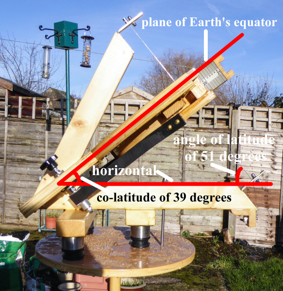 |
Fig. 1. Correction for latitude. |
The sundial is designed specifically for my garden, although it would clearly have been possible to incorporate a mechanism that would permit the dial plate to rotate about an east-west axis and thus allow the sundial to be used at other latitudes.
*** *** *** *** *** *** ***
Clock time, in relation to where I live, is either the mean solar time at Greenwich (GMT) or that time plus one hour (British Summer Time or BST).
My garden is at a longitude of 1.178 degrees west. This means that when it is solar noon on the Greenwich Meridian, it is 4.7 minutes before solar noon in my garden.
My sundial is designed specifically for my garden. The timescale is, therefore, fixed such that, without correction for the EoT, my sundial will always show solar time as being 4.7 minutes later than actual solar time in my garden. Solar time as read from my sundial, therefore, appears to match solar time at Greenwich. This is a very simple thing to achieve with an equatorial sundial because the time graduations are equally spaced, and so the timescale can simply be displaced by the appropriate time interval.
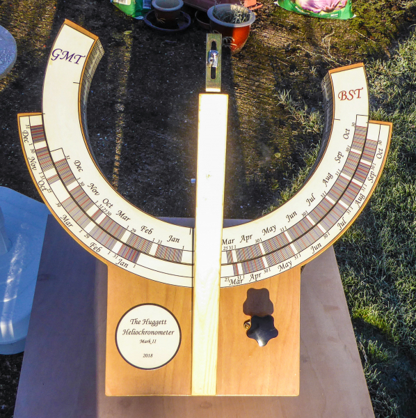
For reasons related to the design of the adjustment scales, the timescale graduation that aligns with the longitudinal axis of the dial at its southern end, when there is no EoT correction, relates to British Summer Time. This, due to the longitude correction, represents a time of 13:04.7 as shown in Fig. 2.
Following from this, the timescale graduation that aligns with the lateral axis of the sundial on its eastern side, when there is no correction for the EoT, is 19:04.7.
Similarly, the timescale graduation that aligns with the lateral axis of the sundial on its western side, when there is no correction for the EoT, is 07:04.7.
As previously stated, graduations on the timescale of an equatorial sundial have equal spacings, so it would be straightforward to adjust for other longitudes by positioning the timescale such that appropriately corrected times would appear in the positions described above.
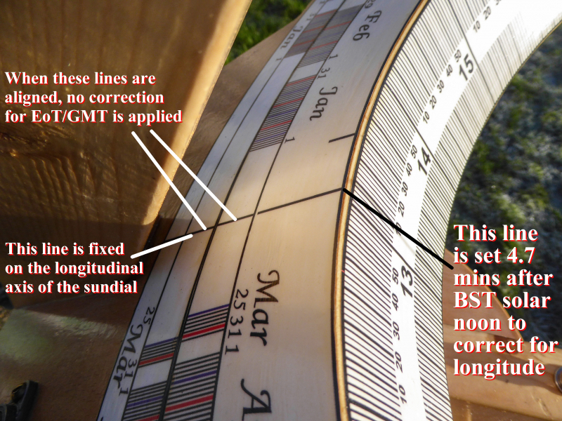 |
Fig. 2.
With no correction applied for the EoT or GMT, the
timescale graduation |
*** *** *** *** *** *** ***
There is no mechanism built into the heliochronometer to set the north-south orientation.
An approximate north-south orientation can be achieved by use of a compass or any other appropriate method.
Due to the accuracy of modern clocks, it is possible to align the sundial accurately by making all other relevant adjustments and then orientating the instrument such that it reads the expected time.
*** *** *** *** *** *** ***
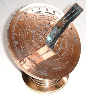
The Sol Horometer method of correcting for the EoT involves the alignment of a pair of lines for the appropriate day of the year (Fig. 4a and 4b).
The two lines that constitute each pair are located on two separate circular scales that can move in relation to one another.
If the line-pairs are correctly positioned in relation to each other and the timescale, then the resulting angular movement of the timescale, caused by aligning the correct line-pair for the day, will effect the EoT correction for that day.
Alignment of the Mark II line-pair for 10th December is shown in Fig. 3.
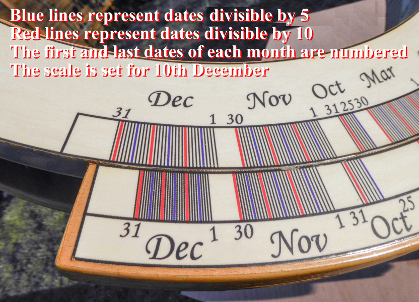 |
Fig. 3. The EoT scale set for 10th December. |
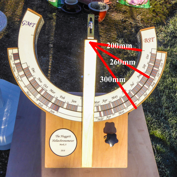
The diameter of the circle on which my scales are mounted, as shown in Fig. 4, is sufficiently large to allow a separate pair of lines for every day of the year. The fact that the centre of the circle does not appear to be on the line of the gnomon is an artefact of the camera angle.
 |
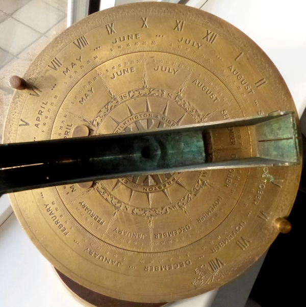 |
Fig. 4. The radii of the circles. |
Fig. 4a.
The scale of a Pilkington Sol Horometer. |
|
|
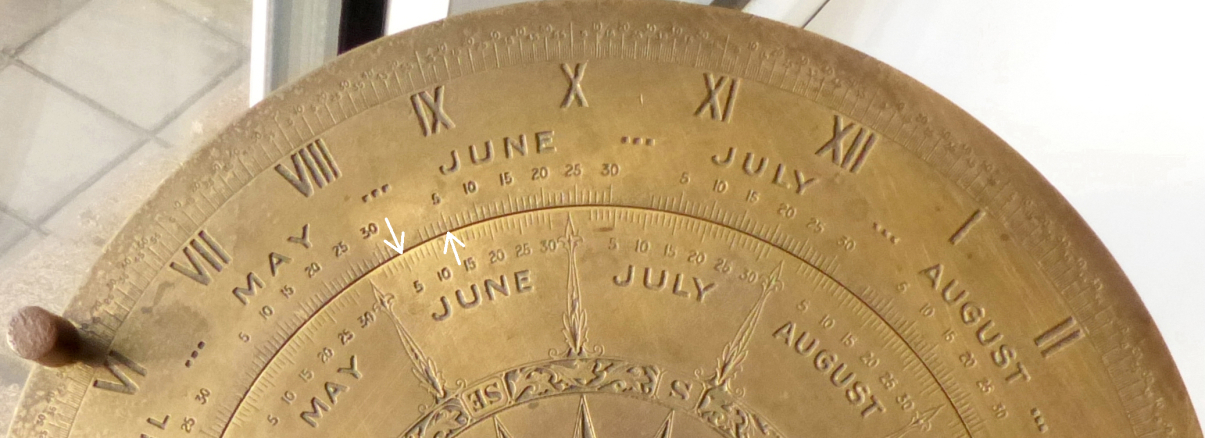
Fig.
4b. The scale of a Pilkington Sol Horometer. The EoT
correction for 5th June would be effected by aligning the
graduations indicated by the white arrows. |
|
In addition, the mechanism that rotates the Mark II timescale arc is sufficiently precise so as to allow simple and exact alignment – see the video, below.
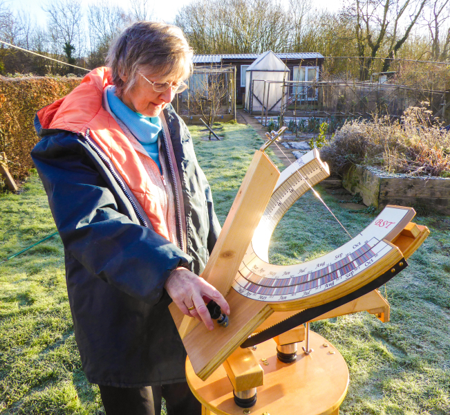 |
Fig. 5. Setting the EoT correction for the day. |
In common with my first heliochronometer, Mark II contains 'original' features. I very much doubt whether they are 'original' in the sense of nobody having thought of them before. They occurred to me independently, however, never having seen a similar example.
The key 'original' feature of the new heliochronometer results from a consequence of the Sol Horometer method of correcting for the EoT.
As described above, the angular rotation of the timescale arc to correct for the EoT on a given day is effected by the alignment of a pair of lines that are specific to that day. One line of each pair is located on the body of the sundial and the other on the rotating timescale arc.
In transferring this idea from a Pilkington Sol Horometer to Mark II, I visualised a single line-pair, for a single day of the year, being attached to the dial plate. One would first set the instrument so that it was properly adjusted to read solar time (or solar time with a longitude correction). The line-pair would then be attached such that the two lines were at their correct angular displacement for that day's EoT correction – one line would be fixed to the static section of the dial plate and the other fixed to the rotating timescale arc. As in relation to the Sol Horometer, alignment of the line-pair would then cause the timescale arc to rotate by the angle required to effect that day’s EoT correction.
I noted that in completing the above process of attaching a line-pair, it would not matter where on the circumference of the dial plate that line-pair was fixed. The EoT correction is effected by the angle of rotation required to align a line-pair. It is thus the relative positions of the two related lines that is important, not where the line-pair, as a unit, is placed.
The location of one line-pair in relation to any other line-pair is also irrelevant as long as the final configuration does not make the scale hard to read.
These facts allowed me to place line-pairs for each day of the year in the configuration shown in in Fig. 6 and Fig. 7.
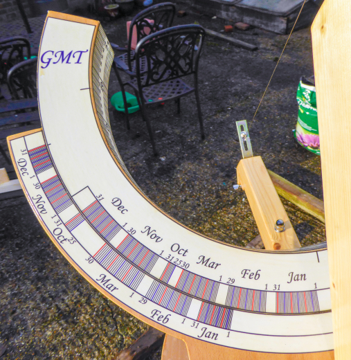 |
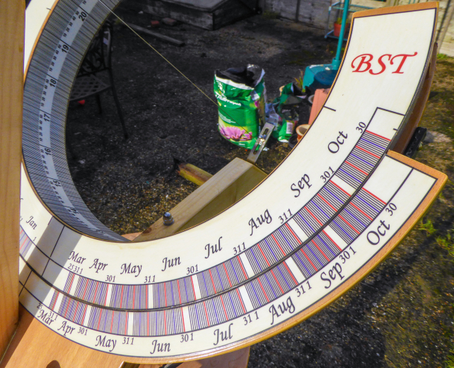 |
Fig. 6. The GMT part of the scale. |
Fig. 7. The BST part of the scale. |
All GMT dates are grouped on the east side of the sundial’s longitudinal axis, and all BST dates are on the west side. The sequence of GMT dates runs clockwise and the sequence of BST dates runs anticlockwise.
*** *** *** *** *** *** ***
As stated above, the timescale graduation that aligns with the longitudinal axis of the dial at its southern end, when there is no EoT correction, is for British Summer Time – which, due to the longitude correction, represents a time of 13:04.7
Each pair of EoT correction lines for GMT dates are displaced clockwise by an additional 15 degrees, or one hour, to reflect the one hour difference between GMT and BST.
GMT changes to BST on the last Sunday in March, and BST changes to GMT on the last Sunday in October. This means that dates between 25th March and 30th March inclusive, and also dates between 25th and 30th October inclusive might, depending on the year, fall within either the period of BST or GMT. These dates therefore appear both on the BST and on the GMT sections of the scale.
There is no line-pair for 31st October on the BST section of the scale as 31st October must always fall within GMT. Similarly, there is no line-pair for 31st March on the GMT section of the scale as the 31st March must always fall within BST.
~*~*~*~*~*~*~*~*~*~*~*~
Key practical issues involved in building the instrument
The scales were drawn with the
use of two free programs that can be downloaded from the Internet.
These were:
Inkscape: https://inkscape.org/en/
Graph: https://www.padowan.dk/download/
Calculations for the scales were made on an Excel spreadsheet.
The scales were printed on
self-adhesive vinyl by pixartprinting: https://www.pixartprinting.co.uk/
Vinyl is durable and, in particular, the printing does not fade
in sunlight.
The adhesive on the vinyl scales was strong enough to hold the
scales in place adequately. When attached to previously varnished
surfaces, however, the scales could be peeled away, once again,
in order to allow final positioning.
The scales were finally varnished with four coats of Ronseal
Crystal Clear Outdoor Varnish, primarily to seal the edges
to the wood so that they would be more resistant to peeling away.
Varnishing is probably not necessary to protect the vinyl.
A copy of a .pdf file
containing all the graphics can be downloaded here: graphics
as a .pdf file.
A copy of .svg file containing all the graphics can be downloaded
here: graphics as a .svg file.
Each scale is a separate object in the .svg file so that they can
be individually scaled.
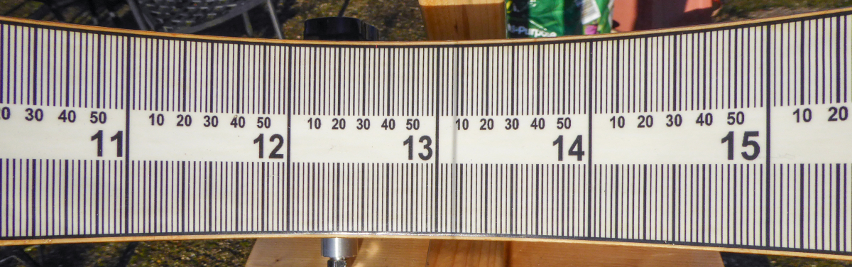 |
Fig. 8. Part of the timescale with the gnomon shadow at 13:07. |
Due to the sun having an angular diameter of 0.5 degrees, the width of the shadow cast by the gnomon onto the timescale is the equivalent of two minutes in time. The umbra of the shadow spans the equivalent of about one minute (Fig. 8).
One minute on the time scale is 0.85 mm in width. The time period between graduations is two minutes.
*** *** *** *** *** *** ***
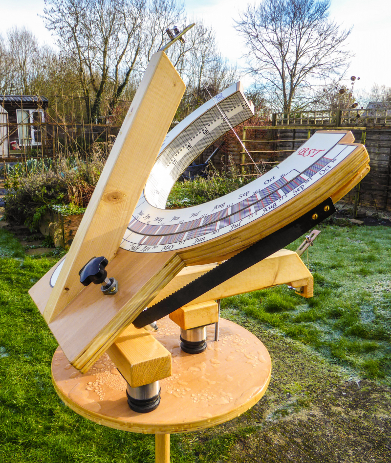
It can be seen from photographs on this page that the timescale is positioned at right angles to the plane of the dial plate. This allows the timescale to be easily read throughout the year.
In addition, the timescale annulus is absent for the section that would represent the period from 21:00 to 06:00. This allows the timescale to be read from 9:00 to 18:00 on days close to an equinox, when the sun is near alignment with the plane of the Earth’s equator – and thus near alignment with the plane of the instrument’s dial plate. These are periods during which a timescale that was a complete annulus would be in its own shadow.
*** *** *** *** *** *** ***
Reducing the thickness of the gnomon is one obvious approach to making its shadow as narrow as possible, but it is difficult to keep a very thin rod straight.
In common with its predecessor, my sundial uses 0.8 mm stainless steel wire for the gnomon, and this is tensioned between its support points. This means that the gnomon can both be thin and totally straight.
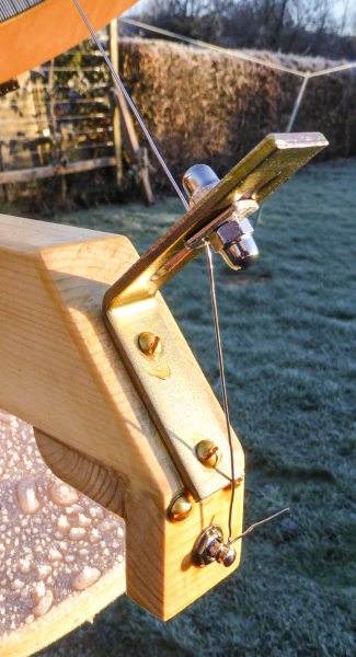
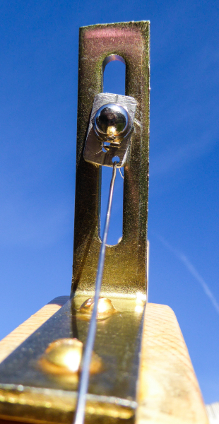
There is a mechanism to adjust the position of the top and bottom of the gnomon wire as shown in Fig. 9.
A guitar machine head made an excellent tensioning mechanism for the gnomon wire. This is also shown in Fig. 9.
 |
 |
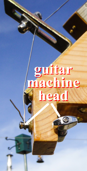 |
Fig. 9. Mechanism to adjust the position of gnomon wire |
||
The domed nuts and threaded bar used in the gnomon support are M6.
*** *** *** *** *** *** ***
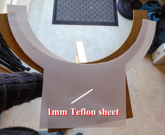
A dry, varnished surface sticks to another dry, varnished surface if they are in contact for any period of time. This adhesion is not great, but it makes for a stiff or jerky beginning to any adjustment. All surfaces that move against other surfaces on this sundial are therefore covered with Teflon*.
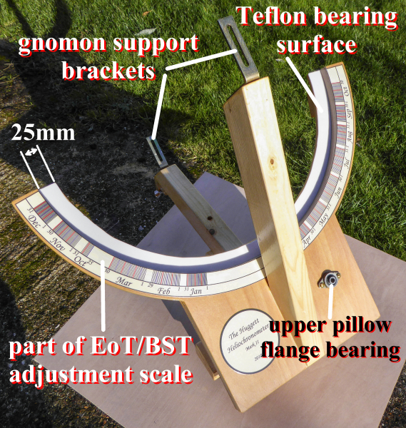
The bearing surface that supports the timescale arc is covered with 1mm thick Teflon* sheet that is sandwiched between the upper and lower sections of the dial plate. The sandwiching is to hold the sheet in place while avoiding the problem of sticking a arc of Teflon* onto the narrow (25mm) bearing surface (Fig. 10 and Fig. 11).
 |
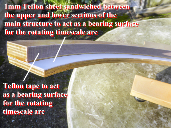 |
Fig. 10. The 1mm Teflon* sheet. |
Fig. 11. Teflon* bearing surfaces. |
The curved vertical surfaces of the timescale arc, and those of the main body of the instrument, that make contact with each other are covered with self-adhesive Teflon* tape.
There are also self-adhesive Teflon* tape strips fixed to the timescale arc where it rests upon the Teflon* sheet bearing surface. The latter also reduces contact area as there are just a few of these strips, rather than the entire arc being covered (Fig. 12).
The width of the bearing surface is 25mm – see Fig. 27 for a dimensioned photograph.
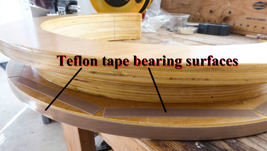 |
Fig. 12. Teflon* tape bearing surfaces. |
The effect of the above is that any surface that moves in contact with any other surface is Teflon* covered. There is, therefore, no sticking, and the mechanical effort required to move the timescale arc has been reduced as much as possible.
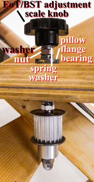
A belt and pulley mechanism linked to a knob, as illustrated in Fig. 13, restrains the timescale arc such that it cannot detach from the body of the sundial. It also allows fine and steady adjustment of the timescale arc in order to align the scale line-pairs – see the video above.
The pulley mechanism is connected by 8mm stainless steel threaded bar. Clearly all the components have 8mm holes or threads.
The timing pulley has a 5mm pitch. The pitch of a pulley, or timing belt, is the distance between two adjacent tooth centres.
 |
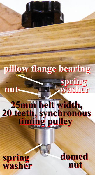 |
Fig. 13. Mechanism that rotates the timescale arc. |
|
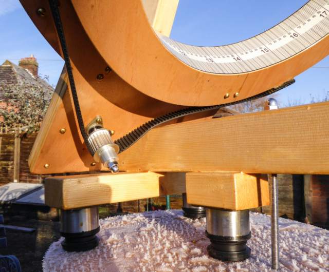 |
Fig. 14. Mechanism that rotates the timescale arc. |
Stop ends are fixed near both ends of the timescale arc, and to the body of the sundial, as shown in Fig. 15. These prevent excess rotation of the timescale arc.
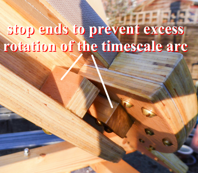 |
Fig. 15. Stop ends to prevent excess rotation of the timescale arc. |
*** *** *** *** *** *** ***
I made a very simple jig that allowed my jigsaw to cut circles (Fig. 16).
The screw, shown in Fig. 16, attaches the jig to the centre of any circle to be cut and acts as a pivot for the jigsaw to rotate around. Any diameter of circle can be cut by drilling a hole for the screw at an appropriate place on the bar.
Mine is not a scrolling jigsaw, but that does not seem to matter if the blades used have a small depth, front to back.
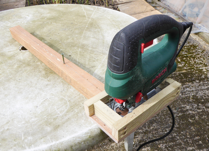 |
Fig. 16. The jig for the jigsaw. |
*** *** *** *** *** *** ***
Experience of my first heliochronometer showed that the plywood from which the sundial is made is well protected by five coats of Ronseal Crystal Clear Outdoor Varnish.
Any point, however, at which water could enter, such as inadequately protected screw holes, led to signs of deterioration.
I have been very careful with the new sundial to thoroughly varnish such vulnerable locations.
All screws, brackets and other fittings are made of brass, stainless steel, aluminium or some other material that cannot rust. Where possible, all such screws, brackets and fittings that are in contact with the wood were varnished over in an attempt to seal any small gaps through which water might enter.
As described above, the scales were commercially printed on vinyl to give greater resilience and avoid them fading in sunlight. The scales were finally varnished with four coats of Ronseal Crystal Clear Outdoor Varnish, primarily to seal the edges to the wood so they would be more resistant to peeling away. Varnishing is probably not necessary to protect the vinyl.
Now this design has been tested, if I were to make a similar dial, I would use marine ply.
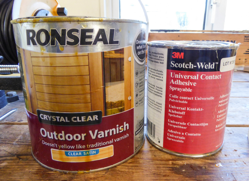 |
Fig. 17. The varnish and the adhesive. |
*** *** *** *** *** *** ***
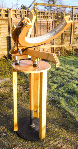
The sundial stands on three adjustable feet designed for use with furniture (Fig 18). Having three points of support allows any object to stand on uneven surfaces. It also simplifies the levelling process.
The level is checked by placing a spirit level, designed for record player turntables, onto one of the crossbars to which the feet are attached (Fig. 18).
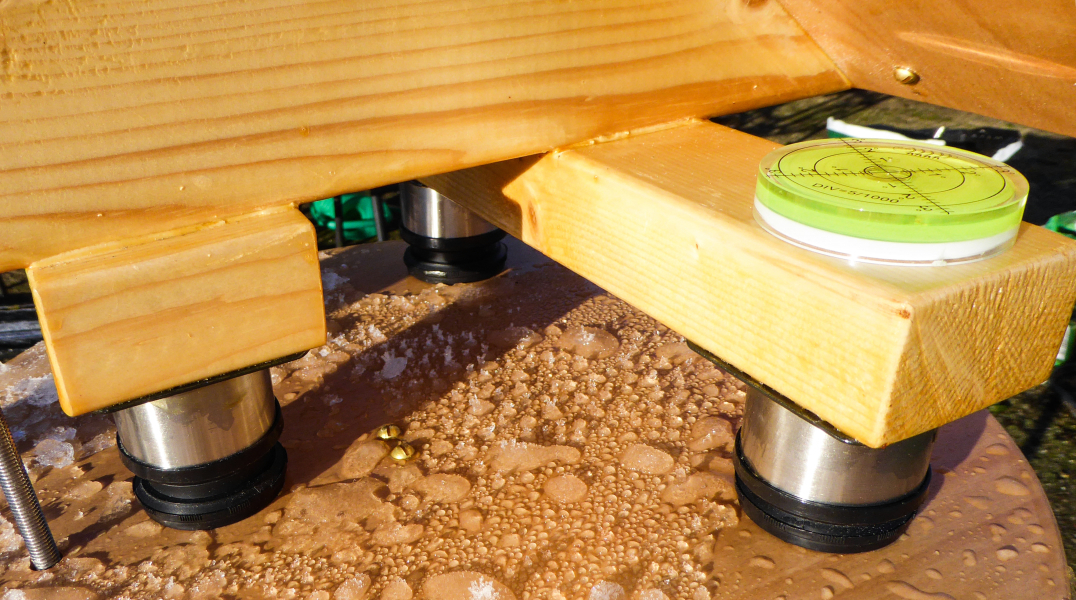 |
Fig. 18. Adjustable feet and spirit level. |
*** *** *** *** *** *** ***
The current design of the table on which the sundial stands is shown in Fig. 19.
The bar that anchors the sundial to its support table is shown in Fig. 20.
 |
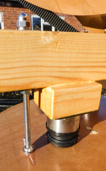 |
Fig. 19. Sundial support table. |
Fig. 20. Bar to anchor sundial to its support table. |
~*~*~*~*~*~*~*~*~*~*~*~
Dimensioned and annotated photographs
The photographs below show the sundial at various stages of construction with key features and dimensions highlighted. I have also included some additional explanatory notes.
I hope these are useful if you would like to attempt to build a similar instrument.
 |
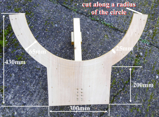 |
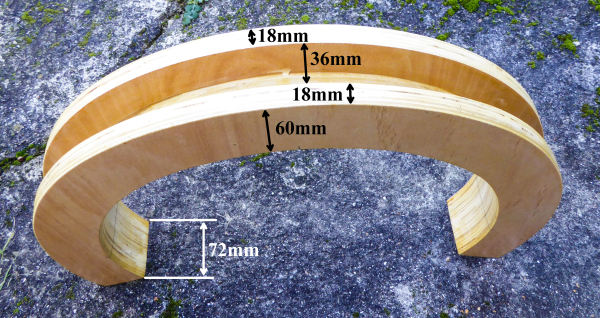
Fig. 21. Upper section of main structure prior to assembly. |
Fig. 22. Lower section of main structure prior to assembly. |
In Fig. 22, the bottom corners of the structure are square. The apparent distortion is an artefact of the camera angle. This section is also symmetrical about the vertical axis of the photograph.
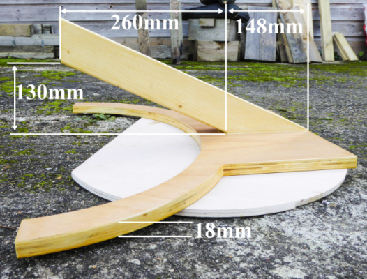
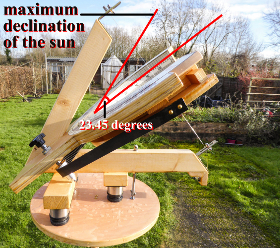
No part of the gnomon support structure must cast a shadow on the timescale. The support structure must, therefore, be set at a position in relation to the plane of the dial plate (equator) that takes account of the sun's maximum declination of 23.45 degrees – see Fig. 23 and Fig 24. No part of the gnomon support structure must be positioned to lie between the plane of the dial plate and the lines that mark the sun's maximum declination.
 |
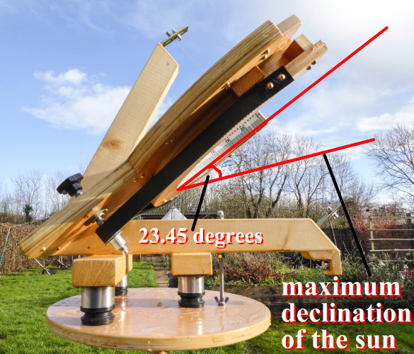 |
Fig. 23. Gnomon support structure and the sun's maximum declination. |
Fig. 24. Gnomon support structure and the sun's maximum declination |
|
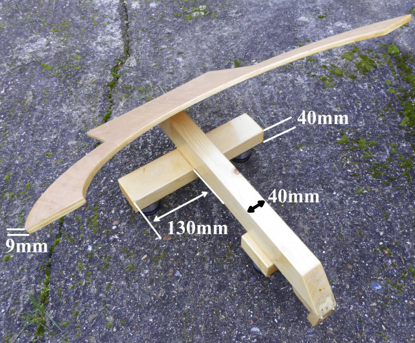 |
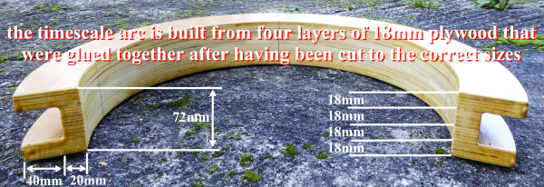
Fig. 25. The timescale arc. |
Fig. 26. Lower section of main structure prior to assembly. |
In Fig. 25, the plywood layers are flat. The apparent distortion is an artefact of the camera angle.
The drive belt is attached to the timescale arc below the bearing surface on which it rotates. This creates a slight downward pull on the timescale arc, leading to small vertical rotation that tends to lift the edge of the timescale arc on the arc on which the two sections of the EoT/GMT adjustment scale meet.
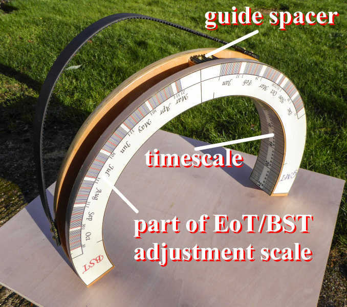
The guide spacer highlighted in the photographs below (magnified view in Fig. 29) is made from a spare section of the drive belt, attached to a block. The drive belt protrudes above the block.
The guide spacer gently touches the underside of the bearing plate on which the timescale arc rotates. It thus prevents the unwanted rotation.
 |
|
Fig. 27. Section of sundial prior to final assembly. |
Fig. 28.
The guide spacer in the final assembly – touching
the underside of |
 |
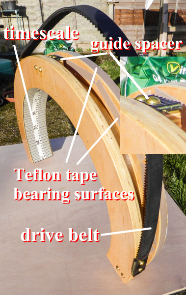 |
Fig. 29. The completed timescale arc assembly. |
|
The drive belt was cut from a 1 metre timing belt with a width of 25mm and a 5mm pitch. The belt width and the pitch obviously matched the timing pulley used to pull it. The pitch of a pulley, or timing belt, is the distance between two adjacent tooth centres.
*** *** *** *** *** *** ***
The accuracy of some aspects of the sundial are not critical, but the accuracy of some other features are very important.
There are six elements of the sundial for which the accuracy of construction must be the best that can be achieved in order to result in accurate readings.
These are:
1 – The angle
of the plane of the dial plate to the horizontal
This had to be confirmed by careful measurement and checking.
2 – The
length of the printed timescale
Although the diameter of the curved surface on which the
timescale is mounted is nominally 400 mm, several factors might
lead to a lack of precision in its final diameter:
*A minor variation in the final diameter of the cut circles.
*Sanding the curved surfaces.
*Varnishing the curved surfaces.
*The thickness of the timescale graphic.
An error in the diameter of the curved surface on which the timescale is mounted has an impact on the accuracy of the timescale, because the circumference of the circle is pi x the diameter. Thus a 1 mm error in the diameter will cause a 3.142 mm error in the overall circumference. This represents a 3.142 x 15/24 = 1.96 mm error on a scale that spans 15 hours. This represents around 2.3 minutes in time. If the centreline of the scale graphic is positioned correctly, this would represent a 1.15 minute error at either end of the timescale.
I wanted to eliminate that error as far as possible and so measured the exact required length of scale when the instrument was ready to have the timescale applied.
The .svg file allowed the timescale to be scaled to exactly match that dimension.
This was checked by printing the scale on paper, prior to ordering the vinyl print.
A copy of a .pdf file
containing all the graphics can be downloaded here: graphics
as a .pdf file.
A copy of .svg file containing all the graphics can be downloaded
here: graphics as a .svg file.
Each scale is a separate object in the .svg file so that they can
be individually scaled.
3 – The
positioning of the EoT/GMT adjustment scale in relation to the
timescale
Please see Fig. 2. once again. The timescale must
be correctly set in relation to the part of the EoT/GMT
adjustment scale that is fixed to the timescale arc –
including the correction for longitude.
4 – The
diameter of the circle at which the two sections of the EoT/GMT
adjustment scale meet
The diameter of the circle along the circumference of which the
two sections of the EoT scale meet is nominally 520 mm. The same
factors as above, however, mean that minor errors could
accidently occur.
The two sections were printed as one graphic so that all line-pairs were at their correct angular displacements.
As in relation to the timescale, the .svg file allowed the EoT/GMT scale to be changed in size. The diameter of the circular curve on which the two sections of the EoT/GMT scale met could therefore be matched as closely as possible to the real diameter of this curve on the instrument.
A copy of a .pdf file
containing all the graphics can be downloaded here: graphics
as a .pdf file.
A copy of .svg file containing all the graphics can be downloaded
here: graphics as a .svg file.
Each scale is a separate object in the .svg file so that they can
be individually scaled.
5 – The
positioning of the gnomon
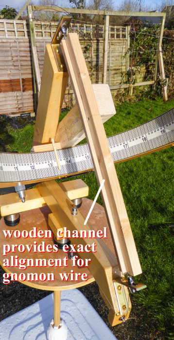
I constructed a simple wooden tool to allow the position and
alignment of the gnomon wire to be set – see Fig. 30 and Fig.
31.
 |
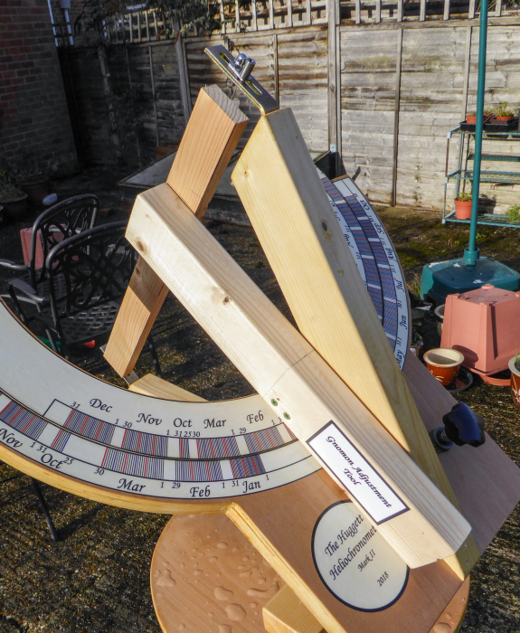 |
Fig. 30. Gnomon adjustment tool. |
Fig. 31. Gnomon adjustment tool. |
The gnomon adjustment tool ensures that the gnomon is at right angles to the plane of the dial plate and at the centre of the circle that defines the timescale arc. The gnomon attachment points allow a reasonable degree of adjustment both laterally and longitudinally.
The final position of the gnomon was confirmed by measuring across the diameter of the timescale arc in several locations. Due to positioning by the gnomon adjustment tool, If the gnomon is correctly set in the plane of the dial plate, it will also be correctly set at other points along its length.
The distance from the timescale to the gnomon was finally 201.25 mm.
6 – The
accuracy of the scale graphics
The scales themselves need to be accurately drawn, but as these
were created on a computer, very high accuracy was automatically
achieved.
~*~*~*~*~*~*~*~*~*~*~*~
*Teflon is a registered trademark of the Chemours company (formerly DuPont). The material is generically known as PTFE or polytetrafluoroethylene.
~*~*~*~*~*~*~*~*~*~*~*~
Reflections on the design of Mark II for those who may wish to build a similar instrument
Further use of the sundial will be needed in my garden to check how it stands up to the elements and to identify any other issues. I will update this page with any relevant information.
At present, however, I believe this to be a fundamentally sound design. It is a development from my first sundial, and addresses all the design weaknesses that I discovered in Mark I: http://bit.ly/The_Huggett_Heliochronometer.
I have been particularly pleased with the scales and the way that the timescale arc fits and moves in relation to the body of the sundial.
If I were building a similar dial immediately, there are one or two tweaks that I might make to individual design elements, but there are none that I would abandon entirely. One such example is the drive mechanism for the timescale arc. It would be interesting to experiment with a smaller drive belt that was anchored within the channel of the timescale arc.
The design weaknesses in Mark I were such that I actively discouraged at least one person from trying to copy it. I can currently see no such problems with Mark II, and I would be pleased to hear from anyone who tries to make his or her own dial based on a similar design.
I would be happy to answer questions if contacted at the email address below.
My scale graphics may be used for non-commercial purposes.
~*~*~*~*~*~*~*~*~*~*~*~
Brian Huggett
is a retired mental health social worker. He enjoys
growing vegetables; performing as a singer/guitarist and
writing comedy under the pen name of Swan Morrison: heliochronometer@huggett.info |
 |
~*~*~*~*~*~*~*~*~*~*~*~